Function
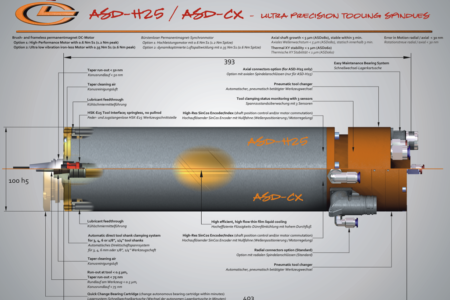
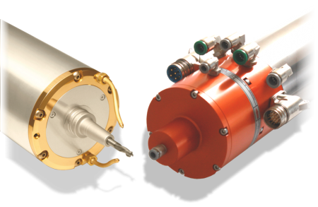
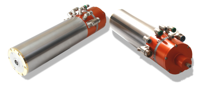
Our spindle models ASD-H25 and UASD-H25 fulfill all your requirements for a high-quality tool spindle to generate high-precision parts with an optical surface finish. They combine robustness and CNC functionality with high spindle speeds for micromachining and low errors in shaft motion for the machining of optical components. The models include the following functions:
- Both models feature an automatic spring-less HSK-E25 tool clamping,
- a high-resolution rotary encoder,
- a highly efficient thin-film liquid cooling,
- tool clamp status monitoring and a robust steel housing with standardized and standard diameters.
Result
If used in CNC machine tools, the user gets outstanding precision, thermal stability, speed, and the ability to create parts with an optical surface finish for the first time. In contrast, for ultra-precision machining, our ASD-H25 and UASD-H25 now enables significantly increased chip loads and an automated tool change to increase productivity at an ultra-precision level.
Both models are also available with axial spindle connectors (ASD-H25A and UASD-H25A).
Comparison of ASD-H25 and UASD-H25 with high-pressure aerostatic bearing technology
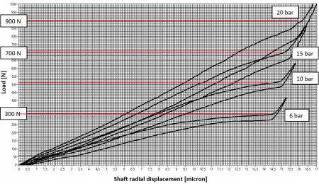
The patented aerostatic bearing system of UASD-H25 and UASD-H25A type spindles with their capillary orifices technology has specifically been designed and manufactured for use with a supply pressure of 20-30 bar. The result is an increase of nearly 300 % in load capacity at the spindle nose compared to the standard models.
The new axial bearing and bearing orifice design reduce the air consumption significantly to provide economical operation even at the higher supply pressures and remarkably increased robustness.
You may need an alternative air compressor to your machine´s standard to operate with the UASD-x models.
| Tool interface | automatic HSK-E25, spring-less (SLH25) |
| Body diameter | 100 mm |
| Motor options | 400 V max., "high-power", 0.7 Nm S1 |
| 200 V max., "high-power", 0.7 Nm S1 | |
| 400 V max., "iron-less", 0.33 Nm S1 | |
| 200 V max., "iron-less", 0.33 Nm S1 | |
| Angular position control | 1 VSS SinCos, 80 lines, zero-flag |
| Nominal speed | 60,000 rpm |
| 80,000 rpm | |
| 90,000 rpm | |
| Tool change system | pneumatic; 4bit tool clamp status monitoring; taper cleaning air |
| Spindle cooling | thin-film liquid cooling |
| Bearing system | aerostatic (ASD-H25) |
| high-pressure aerostatic (UASD-H25) | |
| Accuracy, Dynamics | dynamic tool run-out < 0.5 micron *) |
| shaft error in motion < 30 nm (ASD060H25) | |
| Cutting fluid feedthrough | 2 x spray nozzle at spindle front |
| Spindle connectors | radially oriented |
*) if used with tool holders series UTS-25
| ASD060H25 | UASD060H25 *) | ||
| Bearing air supply pressure | [bar] | 6 - 10 | 20 - 30 |
| Speed | [rpm] | 0 - 60,000 | 0 - 60,000 |
| Static radial ult. load capacity at spindle nose | [N] | 330 | 900 (275 %) |
| Static ult. load capacity | [N] | 550 | 1,300 (255 %) |
| Static radial stiffness at spindle nose | [N/µm] | 41 | 83 (202 %) |
| Static axial stiffness | [N/µm] | 60 | 75 (117 %) |
| Static air consumption | [Nl/min] | 50 | 90 (180 %) |
| Dynamic tool run-out **) | [µm] | < 0.4 | < 0.3 |
| Shaft error in motion **) | [nm] | < 23 | < 28 |
*) all values taken at 20 bar bearing air supply pressure
**) if used with UTS-25 tool holder series
| ASD060H25 **) | ASD080H25 **) | ASD090H25 **) | UASD060H25 ***) | UASD080H25 ***) | UASD090H25 ***) | |||
| General | Automatic tool interface | [-] | HSK-E25, spring-less (SLH25) | HSK-E25, spring-less (SLH25) | HSK-E25, spring-less (SLH25) | HSK-E25, spring-less (SLH25) | HSK-E25, spring-less (SLH25) | HSK-E25, spring-less (SLH25) |
| Body diameter | [mm] | 100 | 100 | 100 | 100 | 100 | 100 | |
| Total length | [mm] | 472 | 472 | 472 | 472 | 472 | 472 | |
| Weight | [kg] | 16 | 16 | 16 | 16 | 16 | 16 | |
| Speed | [Upm] | 0 - 60,000 | 0 - 80,000 | 0 - 90,000 | 0 - 60,000 | 0 - 80,000 | 0 - 90,000 | |
| Tool clamp status monitoring | [-] | 4bit digital | 4bit digital | 4bit digital | 4bit digital | 4bit digital | 4bit digital | |
| Motor option "high-power", max. 400 V | Type | [-] | 3 phases, BL-DC | 3 phases, BL-DC | 3 phases, BL-DC | 3 phases, BL-DC | 3 phases, BL-DC | 3 phases, BL-DC |
| Constant torque | [Nm] | 0.7 | 0.7 | 0.7 | 0.7 | 0.7 | 0.7 | |
| Poles | [-] | 2 | 2 | 2 | 2 | 2 | 2 | |
| max. phase voltage, RMS | [V] | 270 | 370 | 410 | 270 | 370 | 410 | |
| Rated current | [A] | 10 | 10 | 10 | 10 | 10 | 10 | |
| Peak current, RMS | [A] | 20 | 20 | 20 | 20 | 20 | 20 | |
| Shaft Power | [kVA] | 4.3 | 5.8 | 6.5 | 4.3 | 5.8 | 6.5 | |
| Motor option "high-power", max. 200 V | Type | [-] | 3 phases, BL-DC | 3 phases, BL-DC | 3 phases, BL-DC | 3 phases, BL-DC | 3 phases, BL-DC | 3 phases, BL-DC |
| Constant torque | [Nm] | 0.7 | 0.7 | 0.7 | 0.7 | 0.7 | 0.7 | |
| Poles | [-] | 2 | 2 | 2 | 2 | 2 | 2 | |
| max. phase voltage, RMS | [V] | 170 | 205 | 235 | 170 | 205 | 235 | |
| Rated current | [A] | 18 | 18 | 18 | 18 | 18 | 18 | |
| Peak current, RMS | [A] | 36 | 36 | 36 | 36 | 36 | 36 | |
| Shaft Power | [kVA] | 4.2 | 5.6 | 6.3 | 4.2 | 5.6 | 6.3 | |
| Motor option "iron-less", max. 400 V | Type | [-] | 3 phases, BL-DC | 3 phases, BL-DC | 3 phases, BL-DC | 3 phases, BL-DC | 3 phases, BL-DC | 3 phases, BL-DC |
| Constant torque | [Nm] | 0.33 | 0.33 | 0.33 | 0.33 | 0.33 | 0.33 | |
| Poles | [-] | 2 | 2 | 2 | 2 | 2 | 2 | |
| max. phase voltage, RMS | [V] | 260 | 330 | 370 | 260 | 330 | 370 | |
| Rated current | [A] | 5 | 5 | 5 | 5 | 5 | 5 | |
| Peak current, RMS | [A] | 11 | 11 | 11 | 11 | 11 | 11 | |
| Shaft Power | [kVA] | 2.1 | 2.8 | 3 | 2.1 | 2.8 | 3 | |
| Motor option "iron-less", max. 208 V | Type | [-] | 3 phases, BL-DC | 3 phases, BL-DC | 3 phases, BL-DC | 3 phases, BL-DC | 3 phases, BL-DC | 3 phases, BL-DC |
| Constant torque | [Nm] | 0.33 | 0.33 | 0.33 | 0.33 | 0.33 | 0.33 | |
| Poles | [-] | 2 | 2 | 2 | 2 | 2 | 2 | |
| max. phase voltage, RMS | [V] | 160 | 180 | 208 | 160 | 180 | 208 | |
| Rated current | [A] | 9 | 9 | 9 | 9 | 9 | 9 | |
| Peak current, RMS | [A] | 18 | 18 | 18 | 18 | 18 | 18 | |
| Shaft Power | [kVA] | 2.1 | 2.8 | 3 | 2.1 | 2.8 | 3 | |
| Rotary Encoder | Type | [-] | incremental | incremental | incremental | incremental | incremental | incremental |
| Lines | [-] | 80 | 80 | 80 | 80 | 80 | 80 | |
| Signal A/B | [-] | SinCos, 1 VSS | SinCos, 1 VSS | SinCos, 1 VSS | SinCos, 1 VSS | SinCos, 1 VSS | SinCos, 1 VSS | |
| Zero flag | [-] | yes (an./dig.) | yes (an./dig.) | yes (an./dig.) | yes (an./dig.) | yes (an./dig.) | yes (an./dig.) | |
| Bearing System | Bearing air supply pressure | [bar] | 6 - 10 | 6 - 10 | 6 - 10 | 20 - 30 | 20 - 30 | 20 - 30 |
| Air cleanliness, ISO8573 | [-] | 3 or better | 3 or better | 3 or better | 3 or better | 3 or better | 3 or better | |
| Static radial zero position stiffness at spindle nose | [N/µm] | > 40 | > 25 | > 20 | > 70 | > 50 | > 35 | |
| Static radial load capacity at spindle nose | [N] | > 330 | > 300 | > 280 | > 900 | > 800 | > 750 | |
| Static axial zero position stiffness | [N/µm] | > 60 | > 40 | > 30 | > 70 | > 60 | > 50 | |
| Axial load capacity | [N] | > 600 | > 550 | > 500 | > 1300 | > 1200 | > 1100 | |
| Stability and precision | Taper run-out TIR | [nm] | < 100 | < 100 | < 100 | < 100 | < 100 | < 100 |
| Shaft error in motion | [nm] | < 30 | < 35 | < 45 | < 35 | < 40 | < 50 | |
| Dynanmic tool run-out *) | [µm] | < 0.5 | < 1 | < 1.2 | < 0.5 | < 1 | < 1.2 | |
| Spindle soak time | [Min] | < 3 | < 3 | < 3 | < 3 | < 3 | < 3 | |
| Axial shaft growth | [µm] | < 3 | < 5 | < 6 | < 3 | < 5 | < 6 |
*) if used with UTS-25 tool holder series
**) all values taken at 6 bar bearing air supply pressure
***) all values taken at 20 bar bearing air supply pressure
- Bespoke Flange Options
Custom spindle flanges with a shrink fit to the spindle body allow a reliable and straightforward integration of our spindle products into your machine design. Let us know your spindle stock design, and we will take care of the design work and manufacture the right spindle flange.
Contact us about your spindle connections.
Operation below resonances at any speed from zero to top speed
Spindle Operation below Spindle Resonances from Standstill to Top Speed
Our patented bearing technology allows bearing stiffnesses no other aerostatic technology can meet with. The increase in stiffness with speed due to centricugal load and temperature was picked up for the optimization of the rotor dynamics of our spindle products and guarantees a resonance-free operation of all of our spindle products from standstill to top speed. Here the analytically optimized shaft-bearing design makes sure that the spindle speed (= rotation frequency) always stays far below any shaft bending or rigid mode spindle critical frequencies. If not the operation of a spindle at this speed would result in tremendously high vibrations and tool run-out.
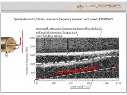
The graph to the right was taken with a high-resolution capacitive gauge measuring against the spinning tool. The gauge not only measures the run-out, but also the vibration of the tool. An FFT analysis can be done for any spindle speed resulting in a resonance spectrum with spindle speed and the residual shaft imbalance as exciting force. This spectrum now includes the exciting frequency (=spinning frequency) as well as any system natural frequency. Doing this at every spindle speed leads to a 3D waterfall-chart with spindle speed as additional dimension. As the amplitude is of no interest at this point it is easire to look top-down where the light aereas now represent peaks (=resonances).
As can be seen on a measurement with our ASD080H25 with a max. speed of 80.000 rpm the exciting frequency (= spinning frequency) never get close to any resonance frequency. For the user this means that at what speed ever he uses our ASD080H25 or any other model spindle speed never is close to a system natural frequency where it is usual for any other spindle on the market. This makes sure that, at what ever speed it is used, vibrations and tool run-out is low.
Dynamic tool run-out and vibrations with speed
Dynamic Tool Run-Out and Vibrations with Spindle Speed
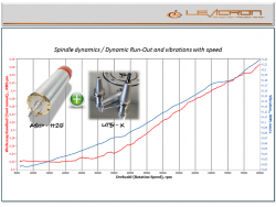
The bearing-shaft design of our spindles are strictly optimized for best shaft dynamics. Means, a light and stiff shaft design combined with high bearing stiffness for a resonance-free operation from standstill to top speed.
In combination with our highly specialized production technology spindle taper a run-out of less than 50 nm can be guaranteed.
As a result the user not only gets a robust high-speed spindle with a load capacity better than with any other aerostatic high-speed spindle, he also gets a dynamically neutral spindle operation over the entire speed range with a dynamic tool run-out of better 0.8 micron.
Shaft error in motion (Error-Motion)
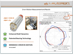
Definition: The value of the so called Error-Motion includes any synchronous and asynchronous spindle error from the theoretical perfect axis of rotation, but without the fundamental (fundamental = run-out).
To perform such a Spindle Error Analysis (SEA) a precisely ground ball is attached to the shaft and one or more gauges measure the radial/axial motion of it. As the roundness of such a SEA-ball (artefact) is much worse than the spindle error itself it becomes clear that an error-separation of spindle and artefact has to take place. This can either be done with a reversal FFT Method where the artefact and the probe has to be rotated by 180° for a second measurement or a multi-probe complex FFT analysis.
Levicron has developed mathematical methods and test benches for the multi-probe measurement of Spindle Motion Errors. As rotation speeds for Levicron products exceed the technical capability of any commercially available solution Levicron developed bespoke hard- and software to verify their products Error-Motion specifications. Our tool spindle models ASD-H25, ASD-H25A and ASD-Cx are specified and verified with a Spindle Motion Error of less than 30 nm.
Tool clamp accuracy and repeatability
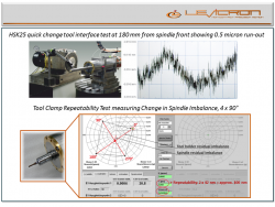
With our highly specialized production a spindle taper run-out of better 50 nm is guaranteed. With the same manufacturing technology our HSK tool holders UTS-x are machined for which we guarantee a tool run-out of less than 0.8 micron and a balancing quality of G0.3 mm/s at 60.000 rpm.
The upper right picture shows a tool run-out measurement of our ASD-H25 at a customer site and at 185 mm in front of the spindle nose. A value of below 0.5 micron confirms the quality and combination of our HSK tool interface and spindle taper.
As a standard test the tool change repeatability of every spindle is tested by our 4 x 90° reversal balancing test at top speed (lower picture). For this the residual imbalance of one of our UTS-x HSK tool holders is measured at 0°. Then the residual imbalance is measured after the holder was rotated by 90° against the shaft. This done three times. The distance from the midpoint of the resulting square to one of its corner represents the tool clamp repeatability where the imbalance is defined as an eccentricity of the tool holder mass. With this method we can guarantee a tool clamp repeatability of less than 0.2 micron.
Axial shaft growth and spindle soak time
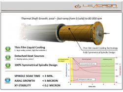
As it can be seen from the graph to the right the thin-film liquid cooling and the cartridge deisgn of our tool spindles ASD080H25, ASD080H25A and ASD080Cx result in a spindle soak time from cold and standstill to top speed and warmed through of less than 3 minutes. For the user this means that after 3 minutes the spindle doesn’t change its properties, doesn’t matter for how long I use it at top speed. Not only that this period is 5-20 times faster than with any other spindle solution, the user also can use the spindle at 80.000 rpm for an unlimited period of time.
The optimized design also compensates for axial growth Where the centrifugal load on the shaft causes a reduction on length, the increase in temperature causes an increase. That’s why a total axial shaft growth of less than 5 micron from cold and standstill to 80.000 rpm and warmed through could be achieved. With our ASD060H25 and ASD060Cx and 60.000 rpm even a value of under 3 micron can be specified.


